
On the evening of February 27, Xiaomi live-streamed the teardown of the LFP blade battery pack for the standard version of the Xiaomi SU7 at its battery pack factory.
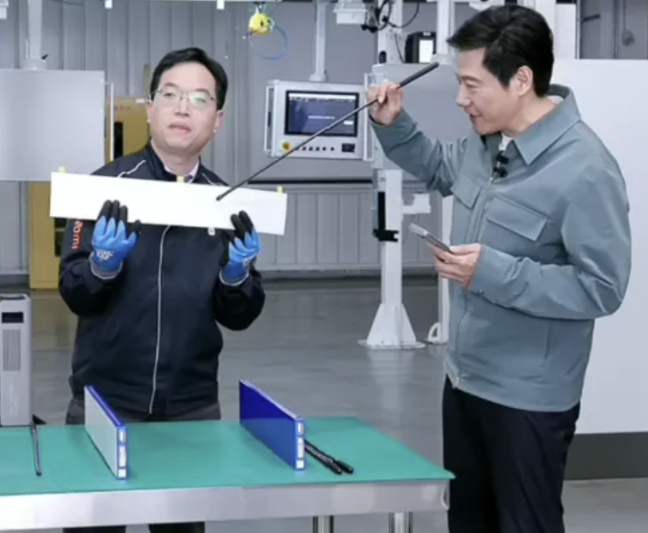
Xiaomi CEO, Lei Jun(right)
Xiaomi SU7 has two models: the NCM model uses CATL prismatic cells, and the LFP model uses BYD blade cells. (A blade cell is one kind of prismatic cell with a two-sided terminal blade shape.)

Xiaomi SU7 official website: https://www.mi.com/global/discover/article?id=3263.
Let’s take a look at the key insights from the live stream.
The assembly process of Xiaomi’s battery pack consists of four core procedures: a. Battery Cell b. Battery Module c. Assembly d. Pack Integration and Testing
Battery Cell
First, let’s focus on the battery cells. Xiaomi sources blade lithium iron phosphate cells from FinDreams Battery(https://www.fdbatt.com/en), a wholly-owned subsidiary of BYD, established in 2019 and specialising in the R&D and manufacturing of LFP “Blade Batteries.”
Each cell is approximately 600 millimetres in length, and the photo attached shows the negative electrode side of the cell. Compared with conventional blade cells, this upgraded design features an enlarged negative electrode post area, which enhances the cell’s high C-rate charge and discharge performance—an engineering design shared with the BYD Han(https://www.byd.com/us/car/han-ev) and Tang L(https://www.byd.com/eu/electric-cars/tang) EV models.
Battery Module
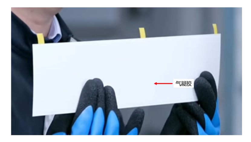
A white aerogel sheet is placed between every two cells, capable of withstanding high temperatures of around 1000 degrees Celsius and effectively mitigating the risk of thermal runaway. It is inferred to be a ceramic fibre aerogel. This design, also adopted on the BYD Han and Tang L EVs, is an upgrade over previous generations and was rarely seen in lithium iron phosphate battery packs for low-budget models in the past.
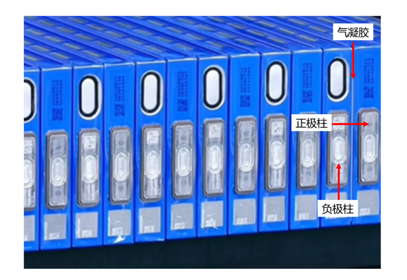
After the large surfaces of the cells are affixed with aerogel, the cell stacking process begins, facilitating the subsequent series connection of the positive and negative electrodes of the cells.
Assembly
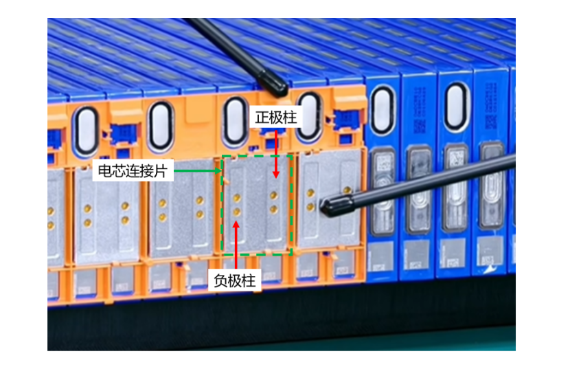
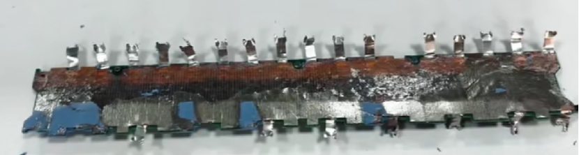
Busbars are laser-welded to the positive and negative posts of adjacent cells, and these busbars are typically made of 1060-O temper aluminium. A notable design tweak here is the integration of two copper inserts in the middle of the busbars, which further boosts electrical conductivity. An injection-moulded insulating plate is installed beneath the busbars.
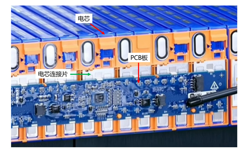
Next comes the installation of the PCB (Printed Circuit Board) for the CMU (Cell Monitoring Unit), which collects basic data such as cell voltage, current and temperature for real-time monitoring by the BMS (Battery Management System). The PCB is populated with a variety of electronic components, including capacitors, transistors, dispersers, inductors, IC chips, resistors and connectors.
It is presumed to be similar in structure to BYD’s PCB.
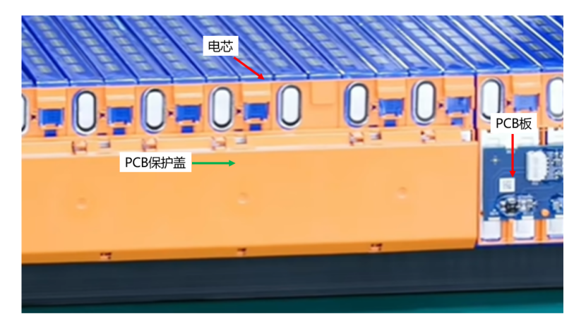
A protective cover, usually made of PP or PPO material, is then mounted on the outside of the PCB for protection.
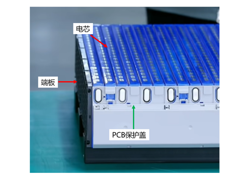
The end plate is required to meet specific mechanical stress requirements to prevent cell deformation under external forces.
A key observation here is: the end plates do not appear to be made of aluminium.
This gives rise to two important questions: what material are the end plates made of, and how is the expansion force of the battery cells managed?
To address these questions, we referred to Xiaomi’s patent, CN218039512U, for battery packs and vehicles, which may provide partial answers.
Material of the End Plates
The end plates are made of Expanded Polypropylene (EPP), with a density of less than 0.2g/cm³—far lower than the 12.7g/cm³ of traditional aluminium end plates—achieving excellent insulation and lightweight performance.
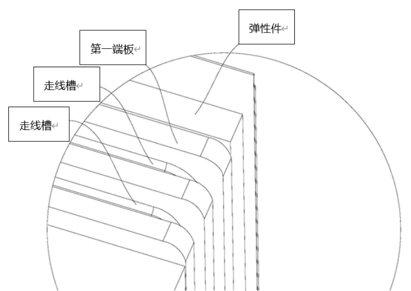
Wire troughs are grooved in the plastic end plates, facilitating cable routing and providing insulation protection even under collision or extrusion conditions.
Elastic Components (Foam)
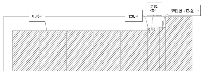
As shown in the patent drawings, elastic components (foam) are installed between the battery pack housing and the module end plates.
This foam is specially designed to absorb the End-of-Life (EOL) expansion of battery cells, compensate for assembly tolerances, and apply pre-compression to the cell modules.
| Key Property | Specific Parameter/Process |
|---|---|
| Preferred Material | PU Foam |
| Thickness (Natural State) | 8mm |
| Thickness (Vacuum Compressed) | 2.5mm |
| Rebound Force (After Film Tearing) | 3psi |
| Expansion Absorption Capacity | Compressed to 75%-80% of its original thickness upon EOL expansion of battery cells |
| Assembly Process | Vacuum compression + PET thermoplastic film sealing; film tearing for rebound and contact after assembly |
When the cell module is in an unexpanded state, the maximum gap between the end plate and the cell side surface is less than 10mm (6mm as cited in the patent), and this gap is exclusively for placing the foam.
At the end of the power battery’s service life, as the battery cells expand, the foam is compressed to 75% to 80% of its original thickness, thereby absorbing the cell expansion effectively.
Once module assembly is completed, the process moves on to the Pack Integration stage.
Pack Integration and Testing
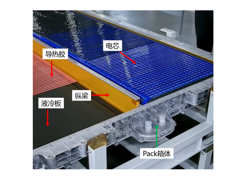
The assembled cell modules are bonded to the liquid cooling plate with thermal conductive adhesive, and the surface of the liquid cooling plate is coated with a black insulating layer. A full-length longitudinal beam, typically manufactured via aluminium extrusion, runs through the centre of the battery pack. The case of the Xiaomi SU7 LFP battery pack is produced using a special die-casting process with Xiaomi’s self-developed Titan Alloy. In comparison with traditional aluminium extruded cases, one-piece die-casting streamlines the manufacturing process and improves mechanical strength.
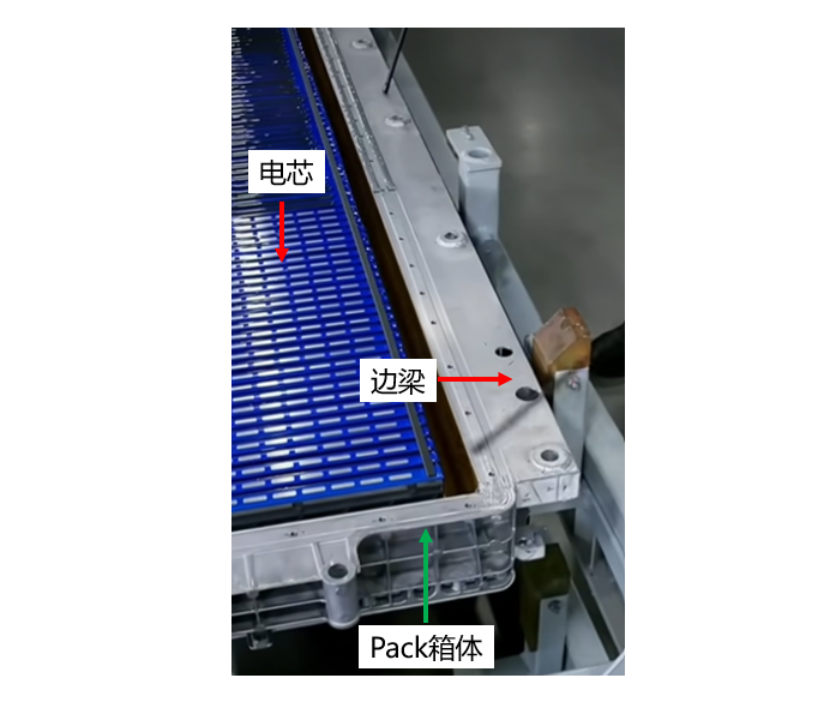
The side beams of the pack remain aluminium extrusions and are fixed to the case by welding.
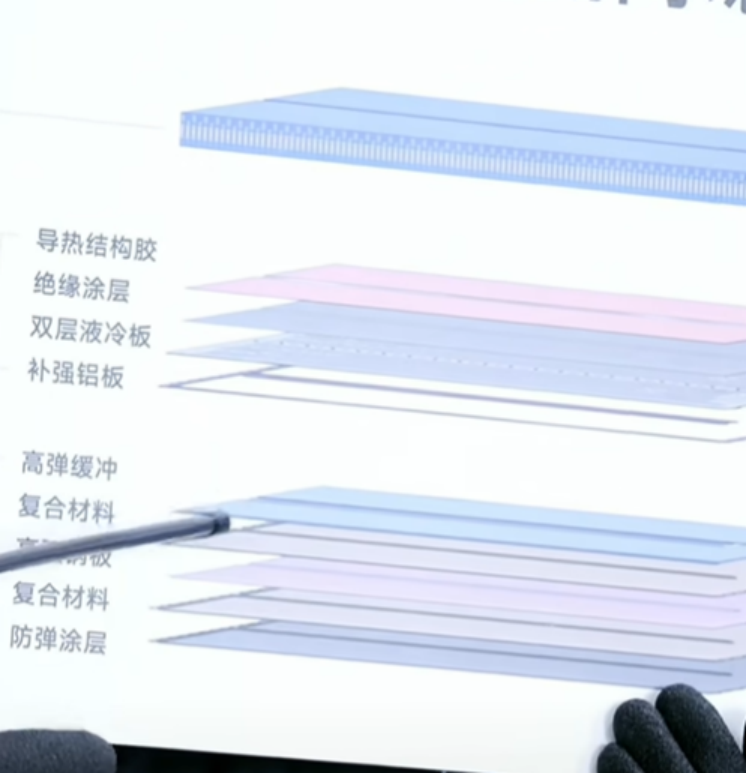
The image attached clearly shows the multi-functional composite layer beneath the cold plate, which includes a high-elastic buffer layer, a polymer composite layer, a high-strength steel plate and a ballistic-resistant bottom guard plate.
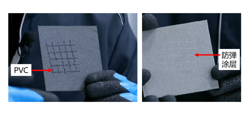
Compared with traditional PVC coatings, the ballistic-resistant coating offers superior scratch resistance (tested by scratching the surface with a 1mm needle).
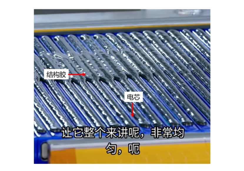
After the modules are placed into the case, a black structural adhesive is applied on top of the cells to secure the battery pack cover.
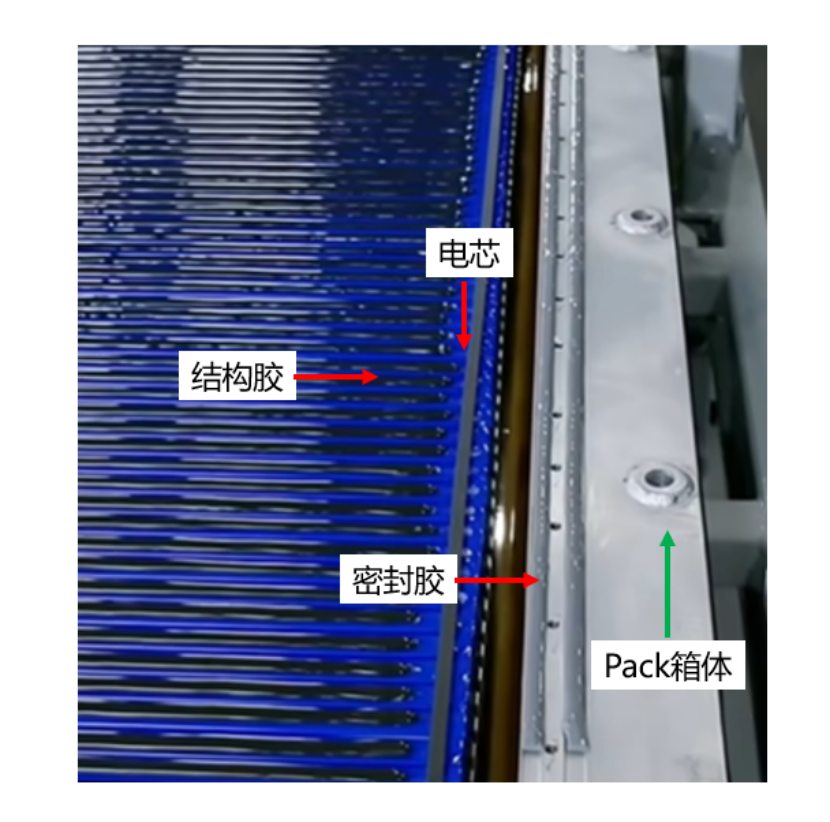
Additionally, a sealant is applied between the battery pack cover and the case to achieve an IP67 or higher dust and water resistance rating. The dual sealant design ensures the structural reliability of the CTB (Cell to Body) structure throughout its service life.
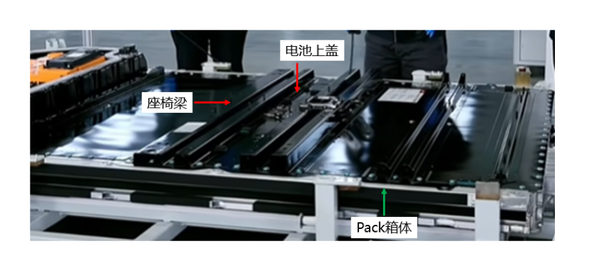
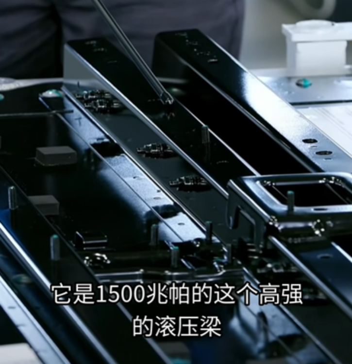
Once the adhesive application is finished, the battery pack cover is installed, which incorporates a 1500 MPa roll-formed seat beam. This beam enhances the torsional stiffness of the battery pack and, when combined with the vehicle’s side sills, boosts the structural strength against side impacts.
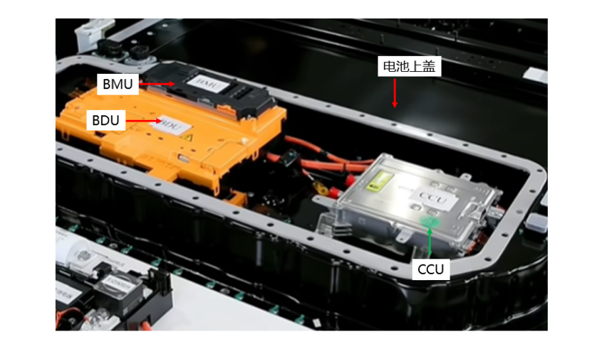
The process then proceeds to the assembly of electrical and electronic components on the second layer of the battery pack, including the BDU (Battery Disconnect Unit), BMU (Battery Management Unit) and CCU (which integrates OBD slow charging and DCDC high-low voltage conversion).
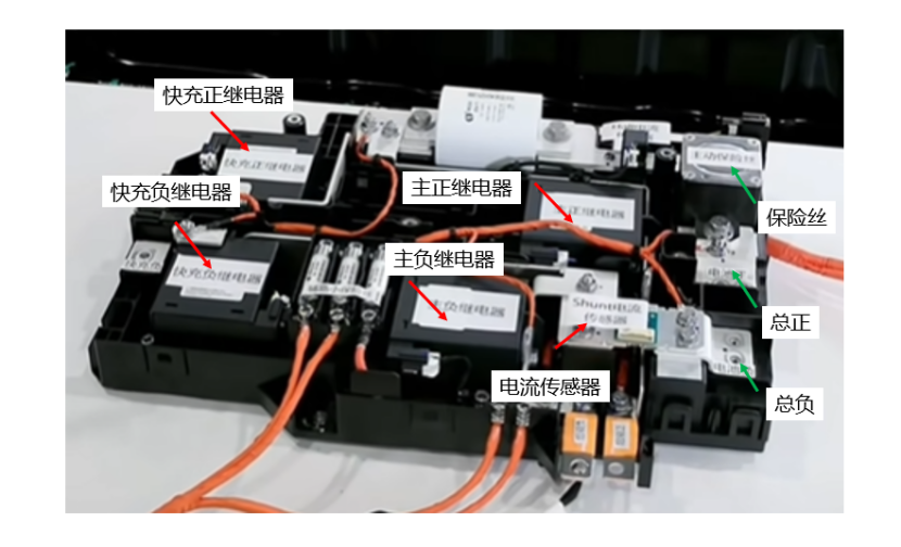
The attached image displays the main internal components of the BDU. The active fuse here can cut off the electrical connection within 4 milliseconds via a built-in pyrotechnic switch, protecting the battery pack in the event of an abnormal short circuit.
Upon the completion of all the above assembly steps, the battery pack enters the testing phase, which comprises a total of 1655 tests, including voltage testing, communication testing, and charge-discharge testing.
All information and images in this analysis are sourced from Xiaomi
Any questions, please comment below! In the next articale we will talk about the Xiaomi SU 7 NCM(CATL Prismatic) version.